Front Panel
The device's front panel is shown in the following figureand described in the subsequent table.
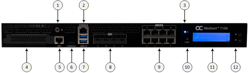
Front Panel Components
|
Item # |
Label |
Description | ||||||
|---|---|---|---|---|---|---|---|---|
|
1 |
|
(Optional) Grounding (earthing) port for banana plug (4 mm). |
||||||
|
2 |
CONSOLE |
RJ-45 port for console management. Note: Using this port requires an RJ-45 to serial USB cable. |
||||||
|
3 |
|
|
||||||
|
4 |
- |
OCP 3.0 Slot for Networking expansion. Note: Currently, not in use. |
||||||
|
5 |
BMC |
1G RJ-45 port for BMC. |
||||||
|
6 |
CONSOLE |
USB Type-C for console management. |
||||||
|
7 |
USB 3.0 |
Two USB 3.0 (5 Gb/s, Type A). Note: Currently, not in use. |
||||||
|
8 |
10G 9|10|11|12 |
Four 10G SFP+ fiber optic ports for the LAN. Note: The ports are supplied with dust covers. |
||||||
|
9 |
2.5GbE 1|2|3|4 5|6|7|8 |
Eight 2.5G RJ-45 ports for the LAN. |
||||||
|
10 |
RST |
Reset pinhole button for resetting the device. |
||||||
|
11 |
- |
LCD module providing two rows for messages. |
||||||
|
12 |
- |
LCD module control buttons (up and down) for scrolling through messages on the LCD. |


